![]()
|
|
Personal web pages ofTim Stinchcombe |
Plan B M23 ASR modificationThere are two problems with the M23:
[Comments on this page apply to the revision level that my example is marked with, Rev 1.1, and I think it highly unlikely that any later version was produced. I also appreciate this page will probably have a very narrow readership: there may not be that many M23s out there in the first place; even fewer owners will have two or more; and of those, I doubt they are even aware that there is a problem when chaining them!] Power supply: my interest in this module grew out of an inquiry as to whether it could be safely run from ±15V split supplies. A quick check of the datasheets of the fitted chips immediately threw up an apparent anomaly: the Analog Devices datasheet for the AD SMP04 Quad S&H chip fitted to the enquirer's module (date code '08) clearly states that the absolute maximum supply voltage is 17V, and yet in the M23 it is being subjected to ±12V, i.e. 24V is applied across the chip. Shortly afterwards I acquired an example for myself: this is fitted with a Precision Monolithics Inc. SMP04 (date coded '91), who I assume originally designed the device. AD acquired PMI in 1990: I've not managed to track down the PMI version of the datasheet, but it is possible that PMI-built devices are happy with a higher-than-17V supply across them: could it be that AD were simply more cautious about the max applied voltage?; could they have put it on a different process which was less 'durable'? (but would this mean that the '08'-coded AD device is old PMI die stock?)—lots of questions, with no definitive answers, so the case isn't proven that the 24V is deleterious to the operation/longevity of the device (though I wasn't going to bet the £11 cost of a chip when designing my replica below, which runs it off ±8V supplies!). It does however seem that the increased supply causes the droop to be worse—this is discussed in the next section. Droop: to check the droop, I simply clocked the M23 with a period of 10 seconds, and fed a small, constant signal of 100mV into it, and scoped each stage in turn:
This shows that each stage drifts up by about 30 or 40mV over the ten seconds, so the droop is about 3 or 4mV/sec, which is a good deal more than the typical figure of 2mV/sec specified for the chip, but well within the maximum value of 25mV/sec. Then I checked out my replica build:
The difference is quite marked, leading me to wonder whether the higher drift might be caused by the too-high supply voltage applied to the chip in the M23. Putting the PMI chip from the M23 into my module gives this:
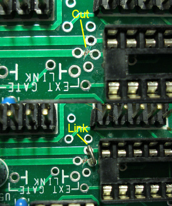
which suggests that the 'oversupply' is indeed having an undesirable effect on the droop! Looking at the tracking on the PCB, I realised it was pretty easy to cut one track and add a link in order to be able to run the SMP04 S&H chip off a single-sided 12V supply only, so I thought it worth giving it a go. It is not really as dramatic as the change in going to ±8V split supplies as shown above, but it is possible it would be considered worth having for some people—the downside of course is that then it will no longer sample negative voltages. Anyhow, here are the resulting traces, perhaps an improvement of x3 or so:
The mod is simple: cut the −12V track (easy to trace back to the power header) in between the vias, as shown; then solder in a small wire link between the vias, from the cut track to the ground rail (again, easy to check); (and note I've pulled the SMP04 chip, designated 'U3', and put a socket in there, as seen in the picture):
(One could even consider putting a switch in, but care would be needed to not switch it whilst the module is powered, as the momentary loss of ground my not do the chip any good at all!) Whilst running off 0-12V it appears the chip is capable of sampling right down to ground, as can be seen at the bottom of the triangle, which dips just below ground, in the following trace:
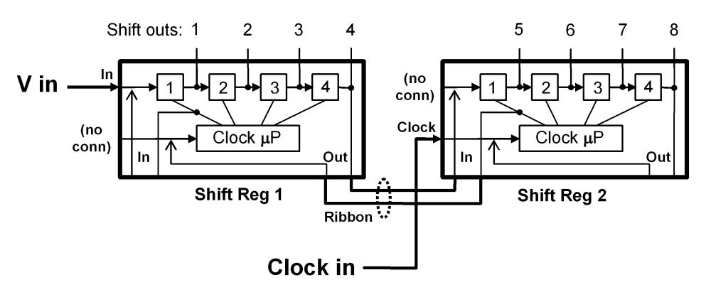
Chaining error: the M23 has a facility to allow two or more units to be chained together, using a small ribbon cable to join them up and pass the shifted voltage and clock signals between them—unfortunately the clock signal passed between chained modules isn't the right one, so that shifting across the eight (or more) stages doesn't work correctly. For the analogue shift register idea to work, when the clock pulse to do the sampling arrives, a later stage must sample the stage immediately prior to it so that it picks up what the voltage was before that prior stage itself is updated, and so on back up the chain—thus the sampling order is from last to first, e.g. 4−3−2−1, as illustrated in the following diagram (the negative-going pulses reflect the SMP04 operation):
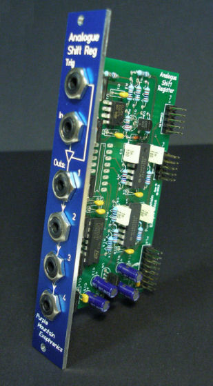
When chained, the M23 simply passes on the same clock pulse as input to the first unit down to the rest of the units in the chain. The effect of this is that the first stage in the second unit in the chain carries the same voltage as the last stage in the first unit (so if either stage 4 or 5 is ignored it behaves like a 7-stage shift register, and not an 8-stage one). The problem can be simulated easily enough, and hence if I had a second module to try it with, it would be easy to show it using an oscilloscope, but then I became intrigued with the idea of how to illustrate it aurally, i.e. without using a scope. Since getting hold of a second M23 could have taken some time, I decided to build my own 'replica' of it, so that I could do some more experimentation:
(The SMP04 dictates an obvious structure for the core of the circuit; lacking the software for the AT89C2051 microcontroller was not really an obstacle as its use is rather overkill for such a simple requirement, which I implemented using a pair of '4013 dual D-type flip-flop chips.) When wired to show the problem, it is indeed simple enough to capture via an oscilloscope—here is set of traces of a ramp being sampled and shifted down the register, with the error highlighted:
With the corrective mod applied to the M23 (detailed below), this is of course what it should look like:
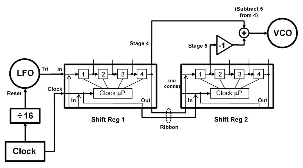
I eventually came up with this idea for a patch so that others might be able to confirm this for themselves without having to use an oscilloscope (click for a larger image):
The basic idea is to sample a triangle wave, take the difference of the last stage of the first module, and the first stage of the second, and feed the resulting CV into a VCO. When operating correctly, because it is a triangle wave being sampled, the difference between successive stages should be a constant: positive as the tri wave increases, and negative as it decreases. Feeding the difference CV into a VCO, we thus hear an essentially alternating tone (the tones aren't quite steady, due to the droop of the S&H inside the SMP04 chip). Here are the various traces concerned, for correct operation, captured on a scope—the orange being the key 'difference' one (and note that the actual patch to achieve this correct operation after applying the mod is necessarily different from that above, and is detailed below):
(I used a Doepfer A-145 LFO for the tri wave; A-146 LFO for clock; A-175 to invert stage 5, then added with an A-138 mixer. I used an A-160 to synchronise the tri wave to the clock, to remove the little 'glitches' that will otherwise be present because the sampling either side of the peaks and troughs won't match, but again such a set-up is likely to be more troublesome to achieve precisely without the aid of an oscilloscope, especially as the 145 resets to the zero-crossing!) With the M23 as-is, i.e. without the modification and so exhibiting the error, because there is no difference between stages 4 and 5, the difference CV is zero, and so the VCO outputs a more or less constant tone (though again a little wavering drift can be heard). Here is the corresponding scope shot, and note that stages 4 (blue) and 5 (red) are on top each other, because they are the same:
As mentioned above, the problem arises because the M23 simply passes the same clock signal down the chain of two or more modules: to correct it, a module nearer the front of the chain should be clocked by the pulse from stage 1 of the module following it, which necessarily means that the 'master' clock needs to be fed into the last unit in the chain. This diagram illustrates this—in both this and the one above, I have also shown the internal routing of the clocking signals, and how they are passed between units (click for larger image)
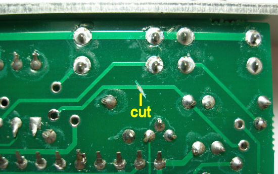
Mod details: the mod is very simple. Cut this track:
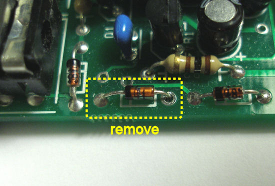
Remove this diode:
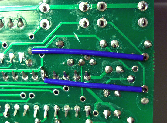
Add two straps between the via/IC pin and the holes of the removed diode, as shown:
[One final thought: my unit has one of the M-TRON '3rd overtone' crystals fitted, known from the M28 (and others) to not run at the desired 24MHz, but at a third of this, i.e. 8MHz, and this indeed turned out to be the case here. Thus the microcontroller is running at a third of the intended speed, and so the sampling pulses output from it will be longer than expected (though they are only about 100 microseconds long anyway). I can't imagine that it would be possible to detect any effects of this without coming up with some clever scheme at the very top-end of the unit's operating frequency!] [Page last updated: 8 Nov 2020] |