![]()
|
|
Personal web pages ofTim Stinchcombe |
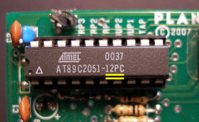
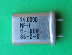
Plan B M28 Tap Clock Synchronization upgrade and other modsSince originally producing this page for the M28 synchronization upgrade (detailed immediately below), it has become apparent that a few other issues with this module could be usefully covered here too: Synchronization upgradeA few minutes experimentation with the feature entitled 'phase lock' on an original M28 will tell you that it does not phase lock—it simply wasn't designed to do that job, and so applying the moniker 'phase lock' was a poor choice that was only ever going to lead to customer disappointment. Fortunately Phil Gallo, the original developer of the software for the on-board microcontroller (the 'firmware'), was willing to work together on a collaborative effort to produce a new version which behaves very much closer to what a user would expect from a function called 'phase lock'—it is perhaps not acting as a phase-locked loop in the usual sense, but the output is able to very closely synchronize with the input, and also track it as it changes (within certain limits of course). In addition a number of users have noted that the M28 phase lock input cannot be driven from some other clock modules, including (at least) the Doepfer A-160: it turns out that this is because the A-160 has a high(ish) output impedance, and this interacts with the input configuration of the M28 in a detrimental way, stopping it from seeing the clock transitions. Other modules it won't work with include the Doepfer A-146 LFO, but doubtless there are others from other manufacturers too. To make best use of the upgrade requires performing a minor modification to the input circuitry of the M28, and this modification also overcomes these compatibility issues (and indeed could be performed independently of installing the new software upgrade). The upgradePhil has released a number of web pages describing the upgrade: in essence it requires replacing chip U1 (the big 20-pin IC on the board) with one programmed with the new software; the upgrade also requires that the incoming clock signal be inverted—it is recommended that a small hardware modification is made to the module to accomplish this, but the inversion can be performed by the use of other modules external to the M28. [Update Nov 2010]: Whilst recently adding the bit about resistor R5 at the bottom of the page, I realised I hadn't posted my method of performing the hardware mods to a Rev 1.2 board—whilst I provided Phil with my instructions for modding a Rev 1.0 board, the instructions for a Rev 1.2 board on this page are his method. For Rev 1.2 boards I followed a similar pattern to the 1.0 boards—I have placed instructions for both board revision levels on this page, which is really just a slightly updated version of what I provided Phil in the first place. In addition to greatly improving the units capability to synchronize with the incoming clock, the upgrade includes a new feature that the more synth-DIY-oriented user may be able to take advantage of: the internal 24× frequency has been made available externally as a short pulse at an unused jumper location on the main board; with suitable interfacing to other clock-division modules etc, a new range of possibilities is opened up—for details see Phil's site. Some simple sound samples to demonstrate an upgraded unit's capabilities are to be found further down the page. Upgrade servicePhil has stated that the new software in itself is free-of-charge: however an obstacle exists even for the most ardent DIYer who would want to perform the upgrade him/herself—that of actually re-programming the microcontroller chip, for which suitable programming equipment is required. Thus any third party carrying out the upgrade will necessarily incur costs, and they will obviously be looking to recoup these. As I have access to all the necessary tools, I have volunteered to offer such an upgrade service for UK- and EU-based module owners; Phil has arranged for Big City Music to provide an equivalent service for North American owners. I foresee several options existing, as follows. Option 1: Full upgrade. Send the module to me, I'll re-program the chip and modify the hardware. Cost: £40 Resistor mods: I'll charge another £5 if you want the resistors changing for the accent and/or select mods detailed below. Postal charges: I would generally aim to re-ship the module in the packaging you sent it to me in, and (for UK owners) will use the same service as sent to me, which if either 'First Class Signed-For' or 'Special Delivery' I have factored into the figures above—we will need to discuss costs if anyone has any special insurance requirements over and above those provided by these services; for EU owners the cost will need to be increased to cover higher postage costs. My contact details are here, though I'm also happy to be contacted via the various forums that you may know me from. Information about your module that will be useful to know beforehand: 1. The Atmel micro will be an 'AT89C2051-xxxx' of some sort—here is the original one from my unit:
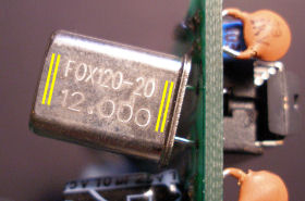
Note down what the '-xxxx' is, as highlighted in the photo. 2. Note down the markings on the crystal, again as highlighted in the photo of mine:
Note that the markings may be on either side, and many types of crystal are possibly installed. Here is an example Mtron (presumed) '3rd overtone' crystal, as all those I've seen so far were running at 8MHz, despite the markings to the contrary:
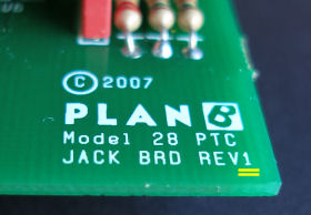
3. Establish the revision level of the 'jack board':
Revisions known to exist are 'REV1' (as shown), and 'REV1.2'. Sound samples[These sound samples are intended to demonstrate an upgraded M28's technical capabilities, and not its artistic ones!] In the first two samples a square wave from an LFO is used as a clock into the M28 'phase lock' input: both the LFO and the M28's 'unmolested' quarters output gate separate EGs feeding their own VCA; two tones are routed through the VCAs—the lower tone (left channel) for the LFO, and the higher (right channel) is the M28. In the first sample I manually adjust the LFO speed: initially it is fairly slow, with the M28 tracking it; I mute each channel in turn, so that the two tones can be better distinguished; I then slowly increase the LFO speed and the M28 follows; when again the LFO is steady, I mute each channel once more—the 'crisp' tracking of the M28 is clear, and gone is the 'drift' that was evident before. I then slowly lower the LFO speed, and again the M28 follows, this time apparently not as accurately as on the way up (when going up a 'shorter period than previously' can be used to reset the internal counts, a luxury not possible when the period is elongated coming down), but it only takes a cycle for it to settle down once the LFO speed is constant. The second sample has a slow triangle wave from another LFO voltage-controlling the first, to show the behaviour in a slightly more dynamic setting. In the final sample we are listening directly to the envelopes, at audio rates. The M28 is able to track the incoming clock up to around 100Hz—as I increase the LFO speed beyond this, the micro in the M28 cannot keep up, and so the output vanishes, returning again once the LFO comes back within range. Since the M28 is primarily intended for syncing to tempos, this is unlikely to be a restrictive limitation! The disclaimer bitAs with just about anything you buy, if you start messing around with it yourself, you will almost certainly invalidate the manufacturer's warranty. This applies equally well to any changes anyone attempts to their M28 (as it does with all mods on my site). This also applies of course if you ask me to make those modifications. Other than a desire to help the synth community out, I have no business or contractual or any connection with either Plan B/Peter Grenader, and neither am I acting as their/his agent in any capacity whatsoever. I reserve the right to alter the costings above, without warning, if it becomes clear that I need to, for whatever reason. 8th note accent output amplitude differenceWith both 8th note accent switches toggled up, the blue trace in the following scope shot shows the problem—the first accent is lower than the second (on my module this was about 100mV as shown, but on others it could be more or less than this, and conceivably could be higher, not less): 
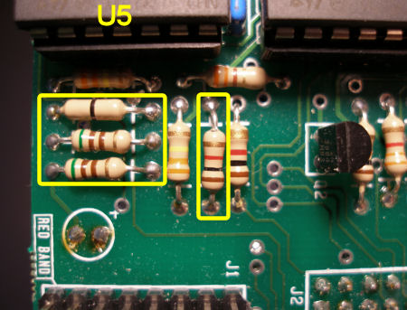
The red trace is the LFO 'clock in' to the phase lock input, as a timing reference so the two blue accents can be distinguished; the green and orange traces are the two accents on an expanded timebase, overlaid for a better comparison. The effect can be readily heard by modulating a VCO with the accent out: in this small sound sample, high and low pitches alternate as the VCO reacts to the accent pulses, and the two high pitches are clearly different, due to the different accent amplitudes. The difference in amplitude arises because the analog accents are derived directly from two ostensibly digital output ports of the microcontroller, and unfortunately the ports chosen for these two signals have different characteristics: the second one has a built-in pull-up in the chip, whilst the first requires an external pull-up resistor be added, and it is the difference between the values of the pull-ups that causes the imbalance. This also means the solution is relatively simple—merely change the external one to match the value of the internal one. The following photo shows which resistor to change (it is actually 'R3'), located right next to the micro itself: 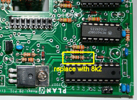
I have had satisfactory results on several modules swapping the original 10kΩ for an 8.2kΩ, as the following traces show (the green and orange are pretty close now), though others have reported needing to go down to 5.6kΩ—this is hardly surprising given the generally poor specification of resistors fabricated inside chips. 
Finally here is a second sound sample of a module after the mod, modulating a VCO as before (note it is not the same module as the traces, but you get the idea...): the two higher pitches deriving from the accents now sound the same. Select change-over voltage levelsThe voltage at the 'select' input determines which pulses come out of the 'serial' output: as the voltage increases from zero, the serial output goes quarters, eighths, and eighth triplets, with nominal change-overs at 2.5V and 5V according to the Plan B M28 page. There are four resistors chained across the 12V rail, dividing it up to give the change-over voltage levels. On my 'rev 1.0' module, these resistors are 510Ω + 510Ω + zero-ohm link + 1kΩ:
giving change-over voltages of near enough 3V and 6V (green is a slowly rising ramp to the select input; blue is the serial out): 
I suspect many Euro modules generating CV-type voltages have a range of only around 0−5V, and so the 6V level could be seen as too high: thus later it may have been decided that a change of values to 510Ω + 510Ω + 3.3kΩ, giving levels of 1.4V and 2.8V (ignoring the fourth resistor for the moment), would better split-up this 5V range. However it looks as though some modules have been built with 2 × 51Ω resistors instead of 510Ω, as I have seen or heard of several 'rev 1.2' modules with these values: 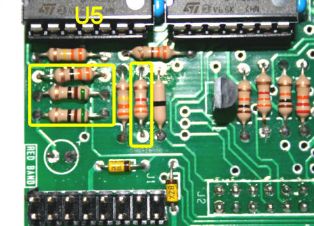
The effect of this is to give more-or-less unusable change-over levels of 0.18V and 0.36V (which is why I do not believe it is intentional): 
If there is a reason for having a non-zero value for that fourth resistor, I don't see it: its effect is to cause a second window of about 0.1V wide during which quarter notes are again output from the serial out. That is, the sequence (for increasing select in) is quarters, eighths, quarters, and then eighth triplets. The trace above doesn't really show this, but it is readily apparent if the select input is fed from a suitable, easily adjusted CV source. In conclusion: changing these resistors from what mostly looks to be an erroneous set of values of 51Ω + 51Ω + 33Ω + 3.3kΩ to 510Ω + 510Ω + 0 + 3.3kΩ produces what should be a nicely tractable range of values for the select voltage (the zero-ohm link can be easily established by soldering a piece of wire across the legs of the 33Ω resistor): 
Missing R5I have seen quite a few Rev 1.2 modules with resistor R5 missing—it is nominally a 330kΩ resistor located near the resistor changed for the 8th note accent mod above: 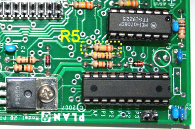
It seems to me that this resistor is performing a legitimate task within the rest/accent logic circuitry, and that leaving it out is more likely to cause problems than having it in (it is pulling-down a CMOS input which otherwise would be floating), and so I have been inserting a 330kΩ resistor at that location whenever I've come across a missing one (in going from Rev 1.0 to Rev 1.2 some of the PCB tracks in the region of R5, particularly ground, have been re-routed, but overall there seems to be no difference to the circuit topology). I can only guess at the reason for it being left out, but I did notice that in the select/serial out circuitry there is a misplaced 330kΩ resistor, R23, which performs no function, located in amongst the resistors of the select change-over levels mod above: 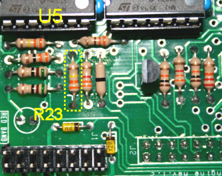
In earlier units a mod involving a zener diode was used to overcome the deficiency introduced by this resistor being in the wrong place; at Rev 1.2 this mod (amongst others) was incorporated directly onto the PCB (one of the yellow zeners in the above photo), and thus my guess is that perhaps at some point it was realised that R23 was useless and so could be omitted, but maybe somehow it got confused with R5 ...? Possible build error in serial out circuit (Rev 1.2)Early units (engine board 'rev 1.0') had a factory-fitted modification: two zener diodes added to the bottom of the board in the 'select' logic of the serial out circuitry, to account for differing voltage levels between 5V- and 12V-referenced parts of the circuit. These zeners were apparently properly incorporated into the PCB at engine board rev 1.2, but having now seen two boards where the wrong type of diodes were installed, I strongly suspect there are more units out there with this mistake, hence the reason for this section. The following photo points out the two diodes concerned: 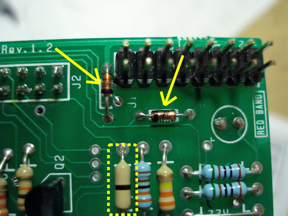
The diodes are meant to be 5V1 zener types, but as mentioned I have seen two units where standard signal diodes, 1N4148 types, were fitted instead. (The photo at the end of the previous section shows an example where the diodes are correctly zener diodes, being yellow in colour rather than the orangey/red that both zeners and signal diodes may be packaged as.) The following traces show the effect of the incorrect diodes. The red trace is the 'serial out' when the select voltage is such that triplets are output, showing rather uneven tops to the pulses—the green trace is what the output should look like, from a unit with the correct zeners (and with a small offset to make it more visible): 
Depending on what use the serial out is put to, this misshapen waveform in itself may not cause any particular problems. However, also shown is the cause of the unevenness: the mauve trace is actually the +5V rail (!) when the problem is present, and the orange trace is what it should look like (namely 5V!)—note especially that the mauve is considerably greater than 5V at some points, and indeed, it is peaking perilously close to the 'absolute max' supply voltage of 6.6V for the large AT89C2051 microcontroller chip! (Turning the select voltage down to give eighth notes out restores the +5V rail to where it should be.) I have no idea whether prolonged operation in such a condition might actually damage the big chip, but I'm quite sure that I would rectify this if I had this problem on my unit! The solution to this issue is to merely replace any 1N4148 types fitted at these two locations with low-wattage 5V1 zener diodes (4V7's would do equally as well). Also the zero-ohm link highlighted in the first photo in this section should be replaced with a 1kΩ resistor (it acts as the current-limiting resistor for the one zener diode). Technical details of what is happening. The voltage at the 'select' input is applied through resistors forming a divider chain (those above) to three LM324 op amp sections which are acting as open-loop comparators. The output of two of these sections are combined via a simple diode arrangement, and then input to the '2051 processor chip; the third is applied directly to the chip. The two inputs are essentially digital, 'high' or 'low' depending on the voltages down the divider, and the chip generates the serial out as quarter/eighth/triplets accordingly. As the op amps run on a single-sided +12V supply, and the big chip on +5V, the zener mods were added to ensure that no more than 5V reaches the big chip. For the lone OA section, it is literally OA out → resistor → zener to ground → zener cathode to chip, so if the zener is erroneously a signal diode, when the OA is 'high', the full output swing of the OA, ostensibly 10.5V or so, is applied to the big chip (the signal diode is simply reverse-biased, and not 'zenering' as a zener would!). This forward biases the substrate diode/ESD protection diode from the input pin to the supply pin in the big chip, and since the '7805 regulator generating the +5V rail can't sink current, effectively we are pulling the +5V rail up toward the +12V rail! The red trace in the following scope shot is the OA output during the problem, and the mauve is the +5V rail: 
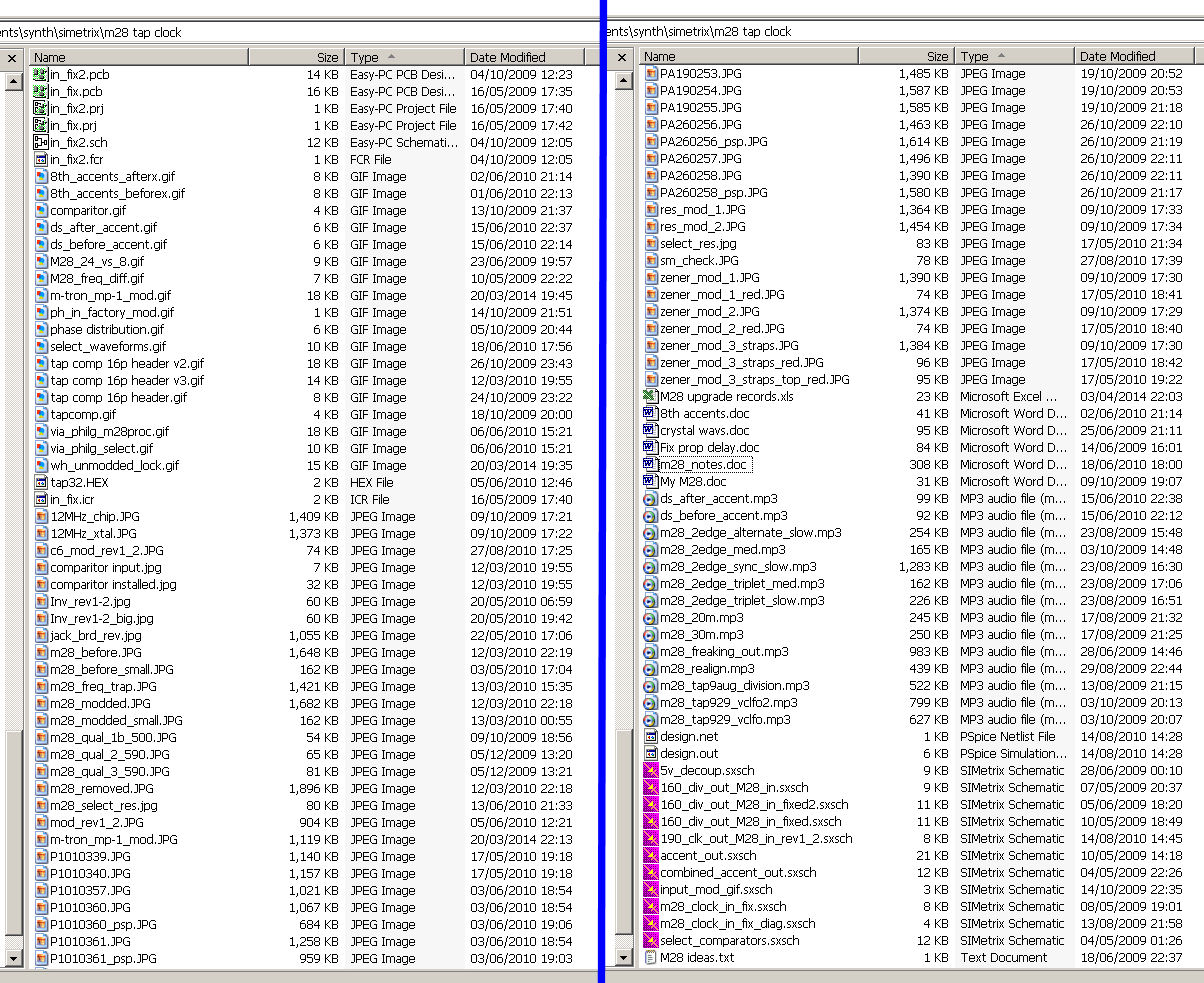
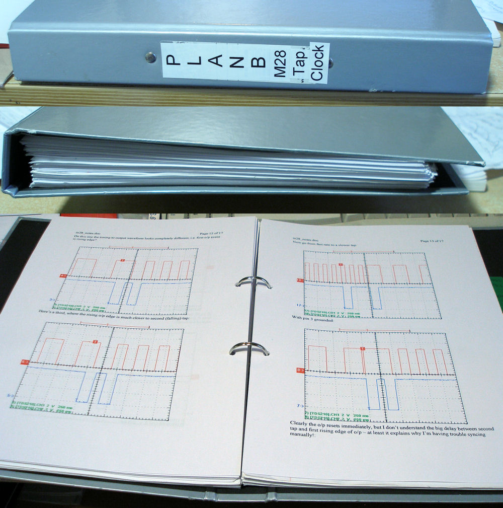
It suggests both that the maximum swing of OA out is reduced considerably due to the large load placed on it (my crude measurement suggests that in this situation the current draw on the +12V rail increases by about 20mA), and that the forward-biased diode at the chip input is not entirely clamping the +5V rail, as the drop looks too big (more than a volt), so there must be some potential divider effect in there too, which changes with the load on the +5V rail, which explains why the waveform is so 'castellated', according to the load on the +5V rail as other chips in the circuit are switching on and off according to all the quarter/eighth/triplet-type pulses around the place. All rather unseemly. I couldn't get the comments to 'thread' properly, but here is a (recent'ish, 2013) fun one on the old Model28SlopClock video (from way back in 2009): Tim Stichcombe did not fix these errors, he - along with Don Kim - merely served as beta sites for the changes done by the original firmware designer Phil Gallo in early 2010. Phil worked on this for close to six months and there were over 50 M28's produced and subsequently sold by two dealers with this firmware incorporated.Here are directory screenshots of the main M28 folder on my computer, and a photo of the ring binder containing all my notes, to give an impression of the quantity of the work involved in the upgrade: 'merely a beta tester' my arse—I was instrumental in driving the upgrade through! [Page last updated: 23 Nov 2016] |