www.timstinchcombe.co.uk


Home

Synth pages
   Synth story
DIY modules
Modifications
   A110 sine shape
A117 clock in
A127 LP/BP switch
A135 indiv outs
A140 self-cycle
A150 switch voltage
A151 2/3 steps
A155 16-steps
A161 clock in
A163 DC couple
IEC power inlet
Plan B summary
M9 bleed-through
M10 envelope
M11 filter
M14 crossfade
M15 sine adjust
M15 others
M17 timer
M23 ASR
M28 upgrade
M32 joystick
M38 ADSR
M38A Expander
Diode Ladder Filters
Korg MS10/20 Filters
Moog paper refs
Fooled by SPICE
Filter pole animations
Serge VCS
EDP Gnat schematics
Old brochures
PE Synth/Minisonic
About me
Photo links
Purple Mountain
Exophrenics
Contact details
What's new
Cheltenham Circular Footpath
The Trouble with Christmas
this night wounds time
Behold the Computer
Revolution
Solartron scans

Site map


I have a Facebook page for occasional blog-like articles:

Tim Stinchcombe's Synth Stuff


A-140 Envelope Generator Self-Cycling Modification

It was recently pointed out to me (Jan 2014) that I didn't have any detail of this mod here on my website. Several reasons caused this: the mod was worked out a long time ago (in 2003), before I had any means of obtaining a hardcopy output from an oscilloscope, so I wasn't able to present any output showing what the oscillating A-140 looked like; but mostly it was because I'm not that convinced that it is actually a very useful modification to do—to me it feels a bit 'second rate', but I guess I should let others judge for themselves how useful they might find it. (I often do things just for the sake of seeing if it can be done, or to see if I can actually do it, and this mod is very much in this camp.)

The mod makes use of the op amp used to generate the inverted envelope out, and so that particular function is sacrificed: additional components turn the op amp into a comparator which generates a 're-trigger' signal once the envelope has decayed down to the 'sustain' level. To make the modified 140 self-cycle the 'gate' must be held 'open' (with a sufficiently high voltage), and the 'inverse output' jack is patched back into the 'retrig' input. It sometimes won't re-trigger if the sustain level is too low (approx. knob settings causing this are given below), and to get it going again the sustain level needs to be increased a little, and then the gate signal needs to be taken low and then high again for the oscillation to get going once more. Since it re-cycles once the sustain level is hit, the output always contains a DC offset (varying with the sustain level), as is readily seen in the traces that follow.

The mod was originally posted to the Doepfer A100 Yahoo group (links below), and I have merely copy-pasted the instructions for doing the mod below as well. But first let's look at some traces of the waveforms that it produces. For each switch setting of 'L', 'M' and 'H' (effectively: fast, medium and slow) I used three different pot settings, with all pots, attack 'A', decay 'D' and release 'R' , set together at one of the same three knob positions, 0, 5 and 10 (again: fast, medium and slow), and then within this ran the unit with the sustain level 'S' at three levels (about) 2 (or 2.5), 5, and 8 (low, medium and high). All vertical scales are the same, with the 0V level being at the bottom of the grid. The annotations show both the vertical scaling, with all being '1V' per (major) division, and so the envelopes swing from just above ground at low sustain levels, up to around 7.5V, and the timebase scaling, again as so many microseconds/milliseconds/seconds per division. Care will be needed when reading the horizontal scales as there is so much variation, and where the settings result in a really fast envelope, but with a comparatively large gap between repeats, I have 'zoomed in' on the horizontal timebase in order to better see the shape and timings of the major part of the envelope. Hence many of the plots below are pretty 'busy', and it will involve a little effort to 'see the wood for the trees'!

It became impractical to capture the longer repeats using my main scope, on which most traces were taken, and so I had to revert to logging the voltage levels at regular intervals (using my older Picoscope) and then plotting the envelopes in Excel—for these plots the horizontal axis actually just shows the elapsed time. In a few of the plots I have illustrated the effect of the big negative spike that results from the envelope resetting to zero (mentioned in the instructions below), but which can be circumvented by ensuring some release is dialled-in—these are annotated as 'S x + R 0', where the 'R 0' shows that the R setting goes against that used for the rest of the traces on that plot.

On the 'H' switch setting, it is possible to get some really skinny envelopes, but with a huge gap between the cycles—the spike of the envelope does go to the same height as others (as seen in the next but one trace), it is just that the logging is not fast enough to capture it:

Here we zoom-in on the spike (using my main scope again), and we can see that the spikes really are quite fast, but which do go to the full height of the envelope (about 7.5V):


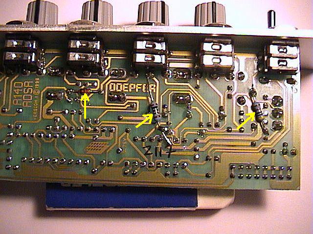
Here is a verbatim copy of the instructions for doing the mod, as originally posted at message #3276 of the Doepfer Yahoo group. The photos were originally uploaded to the photos section. Note that there is one big assumption that the A-140 PCB hasn't changed after all these years!

Hi list,
So, here is my modification to the A-140 so that it can be made to 'auto-repeat', i.e. re-trigger when the sustain level is reached.

It turned out to be a little more complicated than I was at first hoping for because in its first incarnation it didn't perform that well, and so I added a few more bits to improve it. The basic idea is to turn the op amp which currently inverts the envelope (so you lose that function!) into a comparator which switches when the sustain level is reached, and thus feeding this signal back into the 'Retrig.' input makes the envelope continually cycle. To retrigger properly, the switching action of the comparator needs to be crisp, but this tends not to be case when the envelope is 'levelling out' at the end of a long decay, especially if the sustain level is low. Hence an extra resistor and capacitor are used to 'speed up' the comparator switching action.

It works quite well, but it will not repeat if the sustain level is too low. With the component values below, I measured these levels to be approximately:

Time Sustain (Sustain
Range knob voltage)
L 1.5 200mV
M 2 500mV
H 2.5 1V

(all at short to medium delay: they increase gradually with much longer delays, but note the envelope goes up to around 7V). It also (obviously) stops re-triggering when the sustain level is very close to the top of envelope. Another thing is that since the 'Re-trigger' function (as designed in by Doepfer) re-starts the envelope from the _beginning_ of the attack phase, when it re-cycles you can get a sharp negative-going 'glitch', but dialling in some 'Release' slows down the capacitor discharging to the point whereby to all intents and purposes it recycles from the sustain level itself, which looks much nicer.

In spite of all this, there is still lots of room for manoeuvre and experimentation!

The last part of mod (step 8) drops the re-trigger output down to within +/- 8V, so that there will be no problems switching it with an (unmodified) A-150 if you want voltage control of re-trigger off/on. If you are not bothered by this, just leave out this last step and the re-trigger output will be approx. +/-11V or so.

New components needed:
10pF ceramic capacitor
1k, 22k, 47k resistors (22k & 47k not needed if last step not to be done)
1N4148 diode

("Top, bottom, left, right": for the component side, when viewed with the face-plate downwards; for the solder side, face-plate upwards.)

1) Immediately below the TL084 chip find two sets of a 47k resistor (yellow, violet, orange, gold) and a diode, one set above "D6", the other above "D7". Remove both resistors—the top one is seen to have been "R13", the bottom one "R12".

2) Cut the track immediately next to where the left end of R13 was soldered, so that it is isolated from pin 13 of the IC (second pin in from the right) and what was the left end of R12.

3) Locate pin 12 of the IC (third in from the right end, and directly below the left end of R13. Cut the track connected to this (which is actually 'ground')—I did it just below pin 14, the right most pin of the IC.

4) Solder the 1k resistor between the middle connection on the Sustain pot (just below the middle of the middle jack socket) and pin 12 of the IC (third in from right, now disconnected from ground by above cut). (Take care not to get IC too hot...!)

5) Solder the 10pF capacitor where R13 was - bend the left end over the bottom end of the 1k resistor and solder, so that resistor & capacitor are both electrically connected to pin 12 of the IC. Double check that solder has not bridged the cut in the track made in step 2!

6) Solder a plain wire link where R12 was.

7) Locate the 47k resistor above the Decay pot, just above capacitor "C1" (looks like this is actually "R2"). Solder the diode across this resistor, black stripe to the left.

8) Locate the 1k resistor (brown, black, red, gold) between capacitors "C2" and "C3", and remove it (revealing it was "R14"). Solder the 22k resistor in its place. Solder the 47k resistor between the top end of the 22k one (connected to the 'inverse output' socket), and the top pin (negative terminal) of C4, which is actually ground.

Re-label the 'inverse output' socket so you know module _is_ modified! (I called it 'Retrig Output'.)

To test, I suggest patching the envelope output into an A-110 pitch CV input so you can hear what is happening, gate it with a slow-running LFO, and patch the bottom socket (the new retrig output signal) into the re-trig socket.

I shall put some photos of it in the photo section straight away!

Cheers,
Tim

The bottom of the PCB:

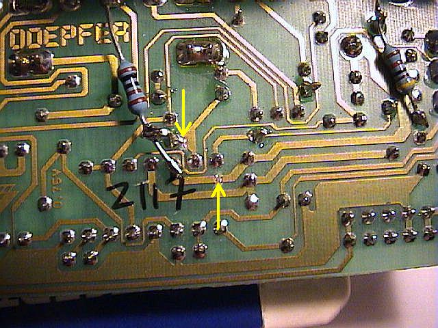
Closer detail on the bottom:
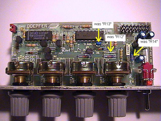
The top:

[Page last updated: 25 Jan 2014]