![]()
|
|
Personal web pages ofTim Stinchcombe |
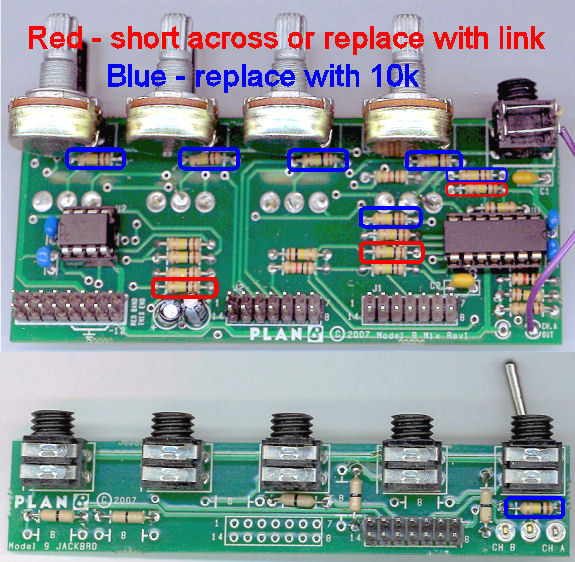
Plan B Model 9 Mixer mods: oscillation and bleed-throughThe Model 9 Mixer suffers from two problems: one of the op amps in the circuit has a propensity to oscillate at high frequencies (way above audio), and there is noticeable 'bleed-through' of a signal to the output even though it is not actually switched through to the output. Both problems are caused by the same thing—unwanted capacitive coupling between PCB tracks—and a few simple changes can kill the oscillation and drastically reduce the amount of bleed-through. Sections which follow describe each of the problems in some detail, but the following photo shows the changes:
[It is not necessary to read or understand the following in order to carry out the fixes above—it is provided solely for a greater understanding of what is actually going on/causing the problems in the first place!] Oscillation: about the first thing I saw on my scope when I hooked it up to investigate the cause of the bleed-through was this:
which is an approximately 280kHz oscillation superimposed on the (about) 1.5kHz square wave fed through the mixer (at this 250μs-per-division timescale the individual cycles of the 280kHz oscillation cannot be observed, as there are about 70 cycles per division; hence all we see is a solid 'bar' of the approx. 1.3V peak-to-peak oscillation superimposed on the square wave). Removing the input signal, the op amp continues to oscillate merrily on its own, from rail-to-rail:
With the fix given above, i.e. shorting/replacing the three red-ringed resistors with links, the oscillation is killed, and the square wave emerges from the mixer as it should be:
The oscillation is caused by a combination of an unnecessary resistor and capacitive coupling between traces on the PCB. The mixer circuit consists of a number of standard inverting op amp set-ups:
Resistor R on the non-inverting input is intended to balance offsets at the output generated by voltage drops across the input and feedback resistors caused by the input bias current at the inverting input. This is a problem for precision applications when using BJT-input op amps, when the current may be sufficient to generate noticeable offsets, but for a JFET-input op amp as used here, these currents are negligible (for the TL074, it is specified as typically being 65pA; in this set-up any offsets are thus in the microvolt region—if this were an issue, then the input offset voltage of the TL074, of the order of millivolts, would probably make it a bad choice). Thus the resistor is not needed (and for such a resistor, its value is poorly chosen anyway, though the full circuit is not shown here): in conjunction with capacitive coupling from the output back to the non-inverting input, it is what allows the op amp to oscillate—this coupling between traces means that in reality the circuit actually looks like this:
SPICE simulation of this circuit shows that it easily oscillates when capacitor C is as little as 0.8pF (but the frequency is then about 1.5MHz, and the amplitude is small); increasing the cap to 4.5pF gives a full rail-to-rail oscillation, at around 280kHz, i.e. closer to what is seen in reality. I have attempted to measure the coupling between the traces on the PCB, using the technique detailed here, and I reckon it to be about 1.5pF, which seems to be inside the range for which oscillation is possible (my scope trace for the measurement is here). I did wrangle with some algebra, but in itself it is probably more tedious than insightful—the graphs derived from it are far more useful. For a simple unity-gain inverting set-up such as we have here, ideally we would expect the frequency response to extend out (with increasing frequency) at 0dB until we get to the unity-gain bandwidth of the op amp, and then a pole will turn it down, as it will necessarily have to be 'inside' the op amp's open loop response. Using a really simple integrator model for the op amp (the response is taken to be 'ωt/s', which is an (infinite) 6dB/octave line crossing 0dB at ωt, the unity-gain frequency) we do see this behaviour, the green line in the following set of traces has a single pole turning the line down:
Also shown is the open loop response derived from the SPICE macro model for the op amp, the blue line, which being more sophisticated than the simple integrator model has more poles in it, which is why, after the turn, it falls more steeply than the green. The undesirable positive feedback resulting from the resistor and the unwanted capacitance adds a pole-zero pair into the transfer function: the combination of values of the cap and resistor are such that the (now) two poles form a complex conjugate pair, i.e. the function is no longer overdamped but underdamped, so we have a resonant peak, which if sufficiently 'peaky' is what causes the circuit to oscillate. The orange trace above shows this behaviour in the integrator-based model; the red line is from the macro model version, showing that the integrator model is perhaps a little too enthusiastic, but it does capture the gross characteristics. Here's the locus of poles, for R=100kΩ, whilst C is varied from 'small' up to 1pF:
The pole on the real axis at the right moves left as C is increased; the other pole is off to the left and moves rightwards; when they meet they split off the real axis, forming a complex conjugate pair, and head around in opposing directions in a circular fashion towards the imaginary axis; when they get there/get close, oscillation will occur. The fix works because lowering R to a short pushes the left-most pole way up in frequency, so there is no possibility of the system becoming underdamped: here is a plot showing the poles as R varies, with C held constant at 1pF; it is zoomed right out (note how small the circle at the right has become!), and in fact is for R from considerably more than a short, from 1kΩ up to 100kΩ—for a near-short, 1Ω say, we'd need to add yet more zeroes onto the frequency values:
Three of the six op amps in the mixer are in this particular circuit configuration, and yet (in mine) only the one was actually oscillating (the main summer in channel A). For the two non-oscillating op amps I supposed this simply to be due to a smaller amount of capacitive coupling from the output back to the non-inverting input: I thus decided to 'up the ante' and soldered a couple of wires, each a few inches long and touching, but insulated from each other, onto the appropriate pins of the chip—this indeed added enough extra capacitance to get both these op amps oscillating as well. I thus recommend replacing all three indicated (red-circled) 100kΩ resistors with wire links. Bleed-through: if a signal is applied to a particular input channel but not switched through to either the 'A' or 'B' output channels, there may be noticeable 'bleed-through' of the signal to the outputs: the effect is quite variable, dependent on the input channel, and 'Ch. 4' seems to be the worst affected. This is caused by capacitive coupling within the circuit, which then tends to act like a differentiator, and hence the effect is more noticeable at higher frequencies. Here is the 'A+B' output with a 1.6kHz square wave input at 'Ch. 4', and not switched through to either output:
Rather than the inverting set-up shown above, the circuit looks more like this, with a small capacitor coupling the (unswitched) input through to the summing junction of the op amp:
In the initial revision of this page I had 'guesstimated' the value of the capacitance to be around the 5pF mark, based on similarity of simulation responses to the above trace. However since then I have attempted to measure the actual value directly from the PCB, using the technique linked above in the oscillation section—this gives me a value around 3pF, revised down a little from the initial guess, but the simulation trace resulting from this value is a pretty compelling case that the issue is caused by capacitive coupling, and that the 3pF probably isn't very wide of the mark, as it is very similar to the observed trace above:
(I also note that this is the 'A+B' output, and so the 'spike' has travelled through three further op amps from the one causing the differentiator action; if we look at the output of that op amp directly, there is a good deal of high-frequency ringing going on, which is also backed-up by simulation results, and this is apparently being filtered out by the further op amp sections in the circuit.) The 'solution' given above, i.e. reducing some of the gain-setting resistors by a factor of 10, really only masks the problem, it doesn't remove it entirely (which would really require re-laying out the PCB, paying greater attention to which traces run close to or cross-over others). However, by replacing all those resistors, the overall gain of the op amp sections concerned isn't changed, but it does divide the gain of the differentiator by 10, as the following frequency response illustrates:
Thus at an given frequency, the amount of bleed-through is now 20dB down (divide by ten) on what it was before. Other than for experimentation purposes I have not actually changed all the resistors in my unit, but there are several positive reports from those who have done so in the thread at ModWiggler where I first suggested the 'fix', i.e. that extra 20dB really is worth having! (Again, please note that the above trace is sourced from a simulation of just the single op amp section causing the problem, so it doesn't really show the true response through the entire mixer—that has a considerable drop-off at the higher frequencies, due to other stability caps in the system, but I elected to keep things simple and decided not to show it!) [Page last updated: 08 Aug 2022] |