![]()
|
|
Personal web pages ofTim Stinchcombe |
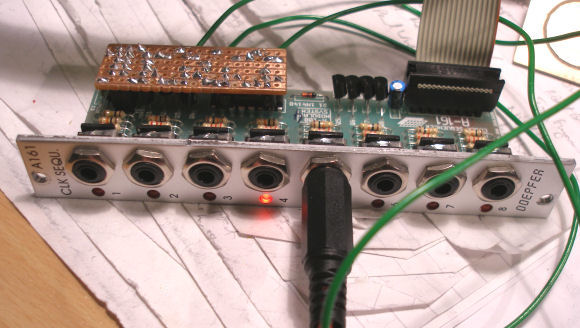
A-161 Clock In and Reset ModIn a recent thread at ModWiggler the idea of modding the A-161 to run independently of the A-160 was raised, i.e. to provide clock and reset inputs direct to the 161. Replicating the basic input circuitry of the 160 is easy enough, but then it occurred to me that mounting the few resistors and transistors needed onto a piece of stripboard which then sits on the 'ST2' header (which normally takes the ribbon from the 160), would be a particularly simple solution. Here is one I made up in situ on the 161, which is being powered through its own power ribbon connector, with it actually resetting itself after four steps (the output from the fifth stage feeds back to the new reset, but the connections are out of shot):
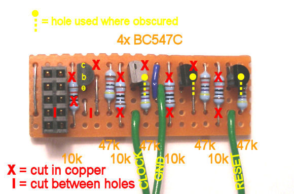
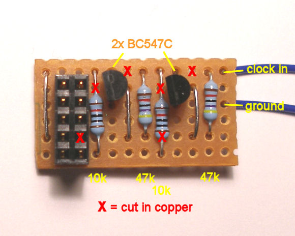
All it takes is: a piece of 18 holes × 6 strips stripboard; 2 general purpose NPN transistors (I used BC547Cs, but they are not that critical, just watch for the pinout being different if you use something else); 4 × 10kΩ resistors; 4 × 47kΩ resistors; a 10-way 0.1" pitch female socket (I used one of these: Farnell 159-3490); and some tinned wire and insulated wire. Here is an annotated photo showing just about all that is needed—where to make the cuts, solder the components, and hook-up points for the new signals:
Note that there are 11 'normal' cuts, i.e. made at the holes, but that there are two other cuts required between the holes. Some of the holes actually used are obscured by the components, due to the distortion of the camera, so the exact holes to be used have been highlighted. Also note that to keep the stripboard as short as possible I have crammed the ground connection in under the one link, which thus needs to be insulated! With care the new transistors can be made to just miss those on the A-161, but if not, some careful bending or twisting of the latter may be needed (and take great care if doing so, as the short leads means they will not have much 'give' in them...). Here is the actual circuit arrangement used:
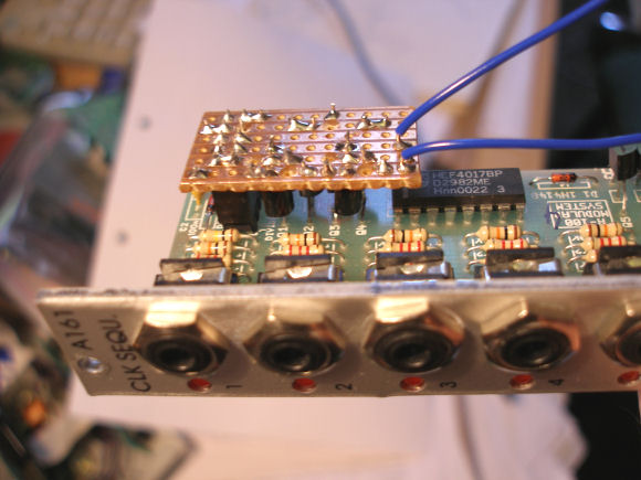
and note that my numbering of header pins is based on the position of the red stripe on the ribbon coming from my A-160, the stripe being nominally 'pin 1', but there is no guarantee that Doepfer make them all the same way round, so refer to the photo for the exact location of which pin is connected to what in the circuit! Connecting up the extra socketsHow this is done is a matter of taste: using another 4HP plate with the extra 2 sockets on seems to defeat the object—one might as well use an A-160 in first place. However if extra space is available somewhere else, then go for it! Another possibility would be to drill small holes in the A-161 faceplate, pass the new wires out and terminate them in 3.5mm line sockets. Clock input onlyMy first effort added just a clock input only, and so requires about half the space and half the components—others might want to do only this too, so here it is:
and here is the annotated photo of it:
[Page last updated: 08 Aug 2022] |