![]()
|
|
Personal web pages ofTim Stinchcombe |
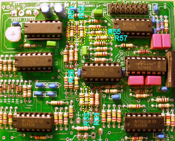
Plan B M14 Dual Voltage Processor crossfade modificationOne of the first things I noticed whilst looking at the crossfade circuit on the M14 was that two resistor values seemed 'out of sorts' with the rest (R31 & R35, highlighted in red in the photo below)—at 33kΩ as opposed to others at 100kΩ, it was clear there was going to be some 'imbalance' in the operation of the circuit. A quick plot of the gain at the output back to each of the input channels in turn, as the Xfade CV voltage was swept, indeed confirmed this to be the case:
It seems these may not be build errors on my unit, as at least one other has reported they have the same values in theirs, hence it seems these are rather 'non-optimal' choices for these resistor values: there is marked asymmetry in the slopes of the up and down ramps of the two channels; the maximum gains of each are different; and the whole crossfade requires a ramp of around 8 or 9V to complete the fade. Fading manually with the pot is likewise lopsided, only this time the steep/shallow difference in ramps affects the channels the other way round:
These shortcomings can be easily rectified with (mostly) simple resistor changes, some small re-wiring to the Xfade pot, and the addition of a few new resistors. These changes make a significant rescaling of the whole thing, which I chose to do for a number of reasons. Firstly I have reduced the total voltage needed to perform the full crossfade, down to around 5V or so, which is much more easily accomplished with other typical Eurorack modules. Secondly, the start of the crossfade, where channel A comes off its maximum, is defined by the saturation voltage of one of the op amps used. In the original design, getting this to occur at some small positive voltage and getting the two curves to cross at the right point would require setting up two finely-tuned offsets, to be defined via two different-valued resistors, and since the saturation voltage will likely vary from unit-to-unit, would probably need two new trimpots. I thus elected to change the 'methodology' of the crossfade: instead of using a unipolar voltage, I have made it respond to a bipolar one—this means the two offsets can be equal (within the bounds of the two zener diodes in the circuit), and it looks as though this gives passable results without the need for trimming. The downside is that it requires re-jigging the Xfade pot arrangement (making it deliver a bipolar voltage too), but the module can still be used with a unipolar voltage by manually offsetting this by using the pot itself, by setting it most of the way anticlockwise (and for that matter, the module can be used with a wholly negative voltage, by setting the pot to a clockwise setting). The 'equal power' feature of the crossfade seems to be achieved by using a dual-linear-segment approximation to a log- or cosine-like curve—making the changes here 'steepens up' one of these segments, which should make the total voltage sweep needed for the crossfade less dependent on the individual op amps' saturation voltages, but should otherwise leave the crossover point unaffected (and hence the equal power-ness of the thing). Here is the plot from my modified unit (note the not-quite-central crossover point is because the pot needs to be manually adjudged to be at its mid-point):
Here is the equivalent plot sweeping the pot manually:
The following photo identifies which resistors need changing, all on the most populous, rightmost board (note this is for a 'Rev 2.1' PCB, and also that the resistor designations on the silkscreen won't really be evident until they are removed!):
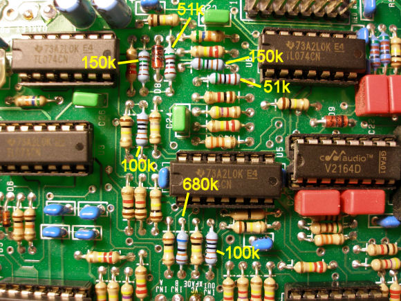
The changes are: turn the trimpot 'VR1' to be fully clockwise (i.e. so it might as well not be there); change seven resistors as follows:
Here is mine after the changes:
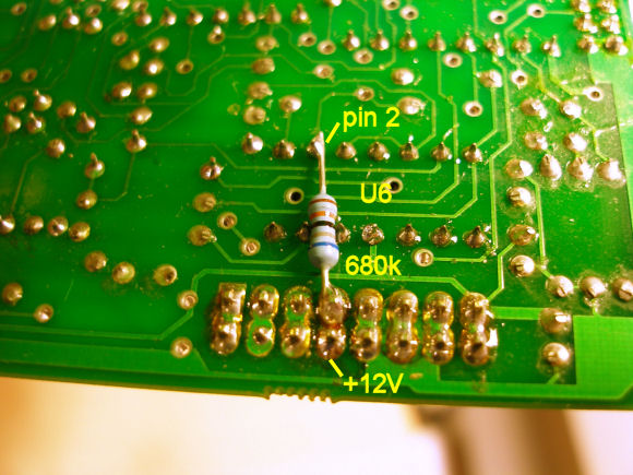
Add a 680kΩ resistor between pin 2 of U6 and the +12V rail:
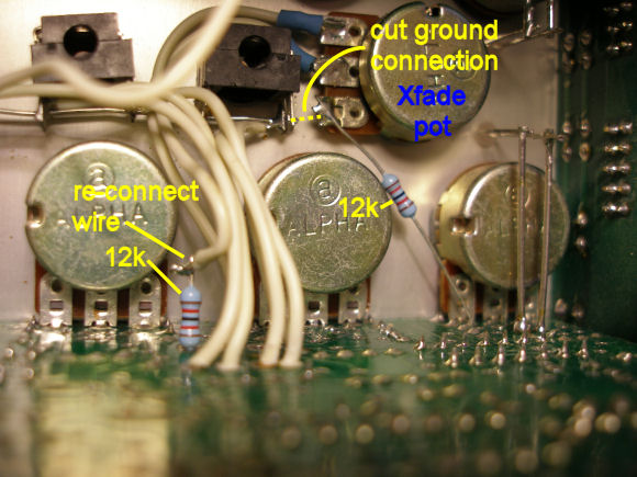
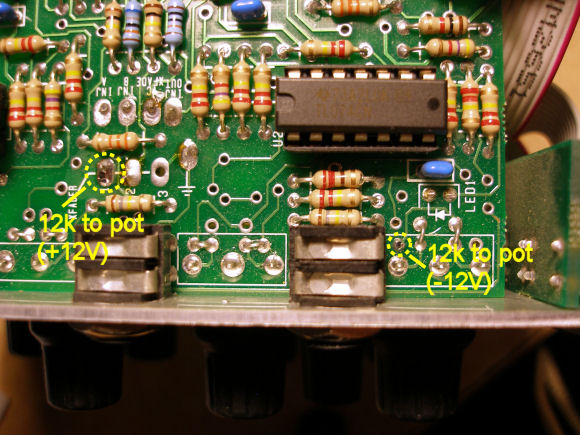
Re-wire the Xfade pot to be between a pair of 12kΩ resistors across the rails: cut the ground wire between the 'VC Xfade' jack and the pot; solder a 12kΩ resistor from the old ground tag on the pot to the -12V rail at the spare hole near the bottom pot on the board (second photo below); de-solder the wire going to the hole marked '1', insert a 12kΩ resistor into the hole, re-solder the wire to the other end:
Locations of the attachment points on the top of the board:
The trimpot. In the original design the 10kΩ trimpot is in series with a 56kΩ resistor, 'balancing' a second 56kΩ in the other channel. This allows the gain of channel A to be adjusted with respect to that of channel B, but since the resistance can only be equal or greater than the other side, this results in gain A only being adjustable to be less than the gain of B! The plot above shows that with this trimpot fully clockwise (and so set to zero), the gains in either channel on my unit balanced reasonably well (they are dependent on a multitude of things like the resistor and zener tolerances, and the op amp saturation voltages etc.), and thus I felt little need to do any more. However if you find you need a little more room for 'tweaking', then changing the 56kΩ in series with the trimpot to a 51kΩ will probably help (it is the one right next to the trimpot; the channel B 56k is two up from R55). Equal power. I have only looked at the algebra of this in sufficient detail to gather that it gets pretty horrid very quickly. It is well known that linear fades suffer from a -3dB 'dip' where they cross in the middle—it seems that to arrive at this we generally consider the two signals as uncorrelated in some way, so that when we calculate the power of the combined signal, we assume that the square of the sum of the signals is actually the sum of the squares, i.e. that we ignore the cross-terms. If we make this assumption and arrange the fading so that they cross at 1/√2 (≈0.71), rather than 0.5, this gets rid of the dip, giving us the 'equal power'. (Some web references suggest the curves need to be logarithmic, others say they need to be sine/cosine—I haven't spent sufficient time studying it to decide either way...) This also means that when the two signals are not 'uncorrelated', for example if they are phase coherent, and so have a fixed phase relationship to each other, such 'equal power' crossfading will actually give an increase of 3dB at the centre point. This is easily demonstrated with the M14 by the simple expedient of feeding the same signal into both channels (so if you do try it, it doesn't mean the M14 isn't 'equal power' or that 'it is broken', it is just the way these things are!). [Page last updated: 24 Aug 2011] |